In the ever-evolving landscape of electronics and engineering, the ability to accurately observe, measure, and interpret electrical signals is paramount. This fundamental need bridges the gap between theoretical design and functional reality, allowing innovators to debug complex circuits, validate performance, and understand the intricate digital conversations happening within their devices. At the heart of this diagnostic process lies a category of tools as critical as the multimeter: measurement instruments.
These devices form the sensory apparatus of the engineer, translating invisible currents and voltages into tangible data on a screen. Among the most powerful and versatile of these instruments is the oscilloscope, a tool that has itself undergone a significant transformation. The advent of the USB oscilloscope has democratized access to high-quality signal analysis, moving it from the realm of expensive, bulky benchtop units to portable, flexible devices that leverage the processing power of the modern computer.
A particularly advanced and crucial variant of this tool is the isolated USB oscilloscope, which introduces a layer of safety and measurement integrity previously unavailable in many compact solutions. The true power of these modern scopes is unlocked not just by viewing raw waveforms, but by interpreting the data they contain.
This is where advanced features like decoding I2C protocol and other serial data streams become indispensable, turning a simple voltage-vs-time graph into a clear log of commands and data. This article will delve into these four interconnected pillars, exploring their individual importance and collective synergy in empowering today’s engineers to see, understand, and create the electronic systems of tomorrow.
What are the Fundamental Roles and Types of Measurement Instruments in Electronics?
The practice of electronics, from the most basic educational project to the most advanced aerospace system, is fundamentally an exercise in measurement. Without the ability to quantify electrical properties, design would be mere speculation, and debugging would be impossible guesswork. This is where the vast category of measurement instruments comes into play, serving as the eyes and ears of the engineer. These devices transform the abstract, invisible world of electrons into concrete, visual data that can be analyzed and understood.
At their core, all measurement instruments are designed to answer specific questions about a circuit: What is the voltage at this point? How much current is flowing? What is the shape of this signal? Is it a clean digital pulse or a noisy analog sine wave? The answers to these questions are the difference between a non-functional prototype and a successful product.
The most foundational of all measurement instruments is the multimeter, a ubiquitous tool capable of measuring voltage, current, and resistance. It provides a single data point, a snapshot of a specific parameter at a specific moment. However, many electrical phenomena are dynamic, changing over time. To capture and visualize these changes, more advanced measurement instruments are required. The oscilloscope is the premier tool for this task, graphically displaying voltage on the vertical axis against time on the horizontal axis, creating a “waveform”.
This visualization allows an engineer to see not just the amplitude of a signal, but also its frequency, shape, noise, and any distortions or glitches. Another critical instrument is the logic analyzer, which is specialized for digital systems, capable of capturing and displaying dozens of digital signals simultaneously to reveal the timing relationships and state of a digital bus.
The evolution of measurement instruments has followed the trajectory of technology itself, moving from analog to digital and now towards increasingly connected and software-defined systems. Traditional benchtop oscilloscopes are powerful, self-contained units with dedicated processing hardware and displays. In contrast, the rise of the PC-connected oscilloscope represents a significant shift in philosophy. These devices, including the common USB oscilloscope, offload display and processing tasks to a general-purpose computer, offering advantages in size, cost, and flexibility.
The capabilities of modern measurement instruments are further extended through sophisticated software, enabling advanced functions that were once the domain of extremely expensive specialized hardware. This software-defined nature is key to functions like protocol decoding, which interprets raw waveform data into structured digital commands, such as decoding I2C protocol data streams. Ultimately, the choice and use of measurement instruments define the precision and depth of an engineer’s understanding, forming the essential link between a theoretical schematic and a functioning, reliable electronic device.
How Does a USB Oscilloscope Function and What Are Its Advantages?
The traditional image of an oscilloscope is a large, heavy, and expensive piece of benchtop equipment, complete with its own dedicated screen, control knobs, and internal processing hardware. While these benchtop instruments remain the workhorses of many professional labs, a paradigm shift occurred with the development and proliferation of the USB oscilloscope. This category of instrument reimagines the oscilloscope not as a standalone device, but as a sophisticated data acquisition peripheral that leverages the immense processing power, high-resolution display, and extensive storage capabilities of a modern personal computer.
But how exactly does this partnership function? At its core, a USB oscilloscope is a compact hardware unit containing the critical analog-to-digital converters (ADCs), signal conditioning circuitry, and memory buffers. Its primary job is to accurately sample analog signals from its input channels at high speeds. This raw digital data is then streamed or packetized and sent to the host computer via the Universal Serial Bus interface.
The companion software running on the PC receives this data and performs the heavy computational lifting: it renders the waveform on the screen, manages the user interface, handles complex mathematical functions like Fast Fourier Transforms (FFT), and executes advanced tasks like decoding I2C protocol signals.
The advantages of this architecture are numerous and have democratized access to capable oscilloscopes. Firstly, cost is a significant factor; by eliminating the need for an embedded computer, display, and a complex front-panel interface, manufacturers can offer a USB oscilloscope with performance comparable to a benchtop model at a fraction of the price. This makes high-quality measurement tools accessible to students, hobbyists, and small startups. Secondly, portability is a key benefit.
A compact, lightweight USB oscilloscope can easily be transported in a laptop bag, turning any computer into a full-featured electronics lab anywhere there is power. This is invaluable for field service engineers or for working on systems that cannot be moved to a lab bench.
Furthermore, the software-centric nature provides unparalleled flexibility. The user interface can be updated and improved without changing the hardware, and new analysis features, such as support for a new serial protocol or a new math function, can be added via a simple software update.
The ability to easily save screenshots, export vast amounts of waveform data for analysis in other programs, and even remotely control the USB oscilloscope over a network are all natural benefits of its connection to a powerful, general-purpose computing platform.
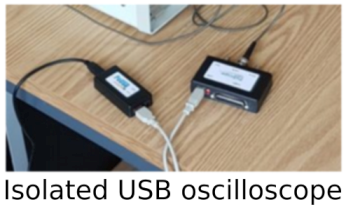
Why is Electrical Isolation Critical in an Isolated USB Oscilloscope?
The convenience and power of a USB oscilloscope come with a hidden, yet potentially severe, risk: the creation of an unintended and dangerous electrical path. A standard, non-isolated USB oscilloscope has its ground reference terminal connected directly to the ground plane of the host computer through the USB cable’s shield. This computer is, in turn, connected to earth ground via its power cord. This setup is perfectly safe for measuring circuits that are also referenced to the same earth ground, such as a breadboard powered by a bench power supply.
However, profound danger arises when attempting to measure voltages in circuits that are not at earth ground potential. A common example is any circuit connected directly to mains AC voltage, like a switched-mode power supply (SMPS). If you connect the ground clip of a standard scope probe to a point in such a circuit that is not earth-referenced, you effectively create a short circuit through the oscilloscope and the computer, potentially destroying the measurement instruments, the device under test, and even causing electrical shock or fire. This is where the isolated USB oscilloscope becomes not just a useful feature, but an essential safety requirement.
An isolated USB oscilloscope is engineered with a critical barrier of protection between its input channels and its USB output. This isolation barrier is typically implemented using miniature transformers or opto-isolators that allow digital data and power to pass through, but completely block any direct electrical current that could create a ground loop or a hazardous short. The isolation is rated to withstand a certain voltage, often 1000 volts or more, which defines the safety margin of the device.
This design means that the ground clips of each isolated channel on the isolated USB oscilloscope are floating; they are not tied to the computer’s earth ground. Therefore, an engineer can safely connect the probe across a component in an off-line power supply or measure the voltage difference between two points on a high-side MOSFET driver without risking a catastrophic short circuit. This capability is indispensable for power electronics work, motor control development, and automotive diagnostics, where floating grounds and high voltages are commonplace.
Beyond safety, this isolation also dramatically improves measurement accuracy by eliminating ground loops that can introduce noise and distort signals, especially when dealing with low-level analog measurements or when decoding I2C protocol on a system with multiple, noisy power domains. An isolated USB oscilloscope transforms a potential liability into a safe, precise, and versatile tool.
How Does Decoding the I2C Protocol Transform Waveform Analysis into Data Interpretation?
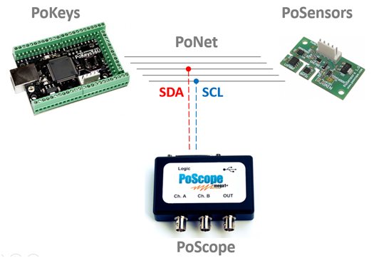
An oscilloscope, at its most basic level, reveals the analog truth of a signal—its voltage over time. When faced with a digital serial bus like I2C (Inter-Integrated Circuit), this view presents two synchronous waveforms: a Serial Data Line (SDA) and a Serial Clock line (SCL). To the human eye, these are just square waves with precise timing relationships; one pulses to clock the data, while the other shifts high and low to represent bits.
Manually translating these voltage levels into binary 1s and 0s, and then further parsing those bits into start conditions, addresses, read/write commands, data bytes, and stop conditions is an incredibly tedious and error-prone process. This is where the powerful software feature of decoding I2C protocol comes into play, acting as a crucial translator that bridges the gap between analog electrical activity and digital meaning.
Integrated into modern oscilloscope software, including that of a sophisticated USB oscilloscope, this function automates the entire process, overlaying the raw waveform with a clear, color-coded, and time-aligned interpretation of the bus traffic.
The process begins with the oscilloscope acquiring the analog SDA and SCL signals with high fidelity, a task for which a well-designed isolated USB oscilloscope is particularly adept, as it avoids ground loop noise that could corrupt the signal integrity. The decoding software then samples these digital channels at the clock edges defined by the I2C standard. It applies a complex digital processing algorithm to the acquired waveform data, identifying the start condition, synchronizing to the clock, and reading the state of the data line on each clock pulse.
It groups these bits into bytes, checks for acknowledge (ACK) or not-acknowledge (NACK) bits, and ultimately packages the whole sequence into its constituent parts: address, command, and data. The result is presented directly on the oscilloscope display as a easy-to-read packet list and a waveform overlay that labels each segment of the signal with its protocol function. This transforms the engineer’s task from one of tedious manual measurement to one of high-level analysis.
Instead of asking “What are the voltage levels at this microsecond?”, the engineer can now immediately see questions answered like “Is the sensor at address 0x52 responding with the correct data byte?” or “Is a NACK causing the microcontroller to halt communication?”. This capability for decoding I2C protocol is transformative, turning the oscilloscope from a simple observation tool into an interactive diagnostic system for embedded software and hardware integration, drastically accelerating development and debug cycles for any project involving this ubiquitous bus.
Conclusion
In the intricate dance of electronic design and debug, the journey from a concept to a functional system is guided by the clear and accurate interpretation of electrical signals. This exploration has illuminated the critical path from foundational tools to advanced analysis, showcasing how modern measurement instruments have evolved to meet the growing complexity of technology. The advent of the USB oscilloscope marked a significant turning point, democratizing high-performance signal analysis by harnessing the power of the personal computer.
This shift offered unprecedented portability, affordability, and flexibility, making sophisticated tools accessible beyond the traditional laboratory. However, with this power came the need for greater responsibility and safety, a challenge met head-on by the development of the isolated USB oscilloscope. This instrument’s integrated safety barrier is not merely a convenience but an absolute necessity for working on modern, non-earth-referenced systems, ensuring both user protection and measurement integrity in the presence of high voltages and noisy grounds.
Yet, acquiring a clean signal is only half the battle. The true culmination of this technological evolution is realized in the ability to move beyond observing voltages and truly understand the digital conversations happening on the wire. This is perfectly exemplified by the process of decoding I2C protocol, a feature that transforms the oscilloscope from a passive observer into an active interpreter. By automatically translating analog waveforms into structured data packets, this functionality unlocks a deeper layer of insight, allowing engineers to debug the logic and communication of their embedded systems with efficiency and precision.
Together, these elements form a powerful synergy: the fundamental capability of measurement instruments, the flexible architecture of the USB oscilloscope, the critical safety of isolation, and the intelligent analysis of protocol decoding. They collectively empower innovators to build, validate, and troubleshoot complex electronic systems with confidence, ensuring that the invisible world of electrons is not only seen but clearly understood.